AS Level Physics 9702
10. DC circuits
Written by: Pranav I
Formatted by: Adhulan Rajkamal
Index
10.1 Practical circuits
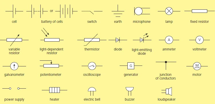
Circuit symbols for AS Level Physics
Electromotive force and potential difference
- e.m.f: energy transformed from chemical to electrical per unit charge driven around a complete circuit
- Potential difference: energy transformed from electrical to other forms per unit charge
Internal resistance
- Electrical resistance shown by power supplies
- Electrical energy is lost as thermal energy as charge passes through the power supply
- \( E = V_R + V_r \), where:
- \( V_R \) is the p.d. across the load (terminal potential difference)
- \( V_r \) is the p.d. across the internal resistance
- \( V_r = Ir \)
- \( V_R = IR \)
Effect of internal resistance on power from a battery
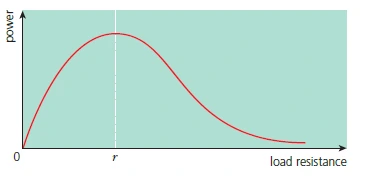
Graph of power delivered to external load against load resistance
- Delivers maximum power to a circuit when the load resistance of the circuit is equal to the internal resistance (\( R = r \))
10.2 Kirchhoff’s laws
Conservation of charge, Kirchhoff’s first law
- Series circuit → components are connected one after another in a loop
- Current is the same at all points
- Parallel circuit → current can take alternative routes
- The sum of the currents entering a junction in a circuit is always equal to the sum of the currents leaving the junction
- \( I = I_1 + I_2 + I_3 + \dots \)
Conservation of energy: Kirchhoff’s second law
- The sum of electromotive forces in a closed circuit is equal to the sum of the potential differences
- If the normal direction of current through a cell is reversed, the cell is recharged
- \( E = V_1 + V_2 \)
- \( E = IR_1 + IR_2 \)
Resistors in series
- \( R = R_1 + R_2 + R_3 + \dots \)
- The combined resistance of resistors in series is the sum of all the individual resistances
Resistors in parallel
- \( \frac{1}{R} = \frac{1}{R_1} + \frac{1}{R_2} + \frac{1}{R_3} + \dots \)
- The reciprocal of the combined resistance of resistors in parallel is the sum of the reciprocals of all the individual resistances
- Always less than the value of the smallest individual resistance
10.3 Potential dividers
- The ratio of the voltages across two resistors is the same as the ratio of their resistances.
The use of potential dividers
- Variable potential divider → variable resistor connected in series with a fixed resistor
- Can be an LDR or a thermistor
- Resistance is affected by changes in light intensity or temperature.
- Potential difference across the variable resistor can be used to operate control circuitry.
- \( V_1 = \frac{R_1 E}{R_1 + R_2} \)
Potentiometers
- A continuously variable potential divider.
- \( V_{\text{out}} = \frac{V R_1}{R_1 + R_2} \)
- A variable resistor is used.
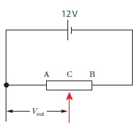
- As the sliding contact moves from end A to B, the Vout increases from 0 V to 12 V
Using a potentiometer to compare the e.m.f. of cells

Potentiometer used to compare cell e.m.f.s
- A center-zero galvanometer is used to detect the current through cell A.
- Used as a null indicator.
- Detects when there is zero current through cell A.
- Current through cell A is zero at the balance point.
- Potential difference across the length of the wire is equal to the e.m.f of cell A.
- \( l_A \) can be used to calculate the e.m.f of the cell.
- \( R = \frac{V}{I} \) (potential difference / current)
- Unit of resistance → ohm (\(\Omega\))
- Controls the flow of current.
- For a given p.d., high resistance means a small current, and vice versa.